Control Box
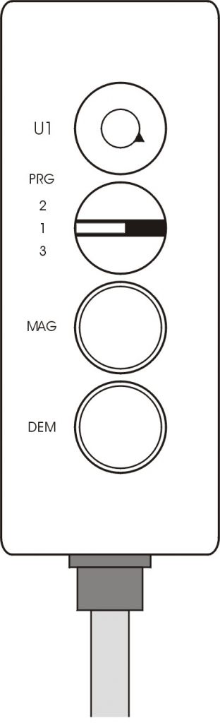
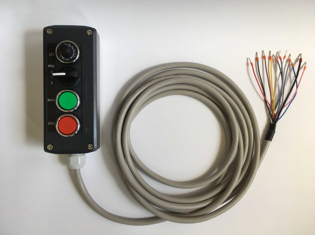
U1 – potentiometer for setting the clamping force level
(output voltage regulation)
PRG – program selection switch
MAG – green illuminated button to start magnetization
DEM – red illuminated button to start demagnetizationDEM – red illuminated button to start demagnetization
Recommended operations before clamping workpieces:
- Clean the workpieces and the surface of the electromagnetic chuck.
- Place the workpieces on the electromagnet over the two poles of the electromagnetic chuck.
Magnetization – CLAMPING
- Press and hold the red illuminated DEM button for at minimum 0.25 seconds.
- During the demagnetization cycle the red button is flashing slowly – the safety contact RELAY RE1 is open.
- Complete demagnetization cycle is indicated by a continuous lighting of the red button.
Demagnetization – RELEASE
- Press and hold the red illuminated DEM button for at minimum 0.25 seconds.
- During the demagnetization cycle the red button is flashing slowly – the safety contact RELAY RE1 is open.
- Complete demagnetization cycle is indicated by a continuous lighting of the red button.
Control Box – External Dimensions and Electrical Wiring
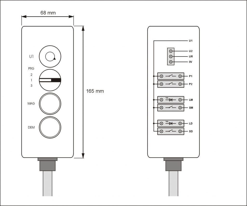
Control Box – Wire Description
| Number | Label | Color | Description |
| 1. | U1 | Black | Power supply voltage +12 V DC |
| 2. | U2 | Brown | Reference voltage for potentiometer +10 V DC |
| 3. | UR | Red | Potentiometer output voltage 0 to +10 V DC |
| 4. | 0V | Blue | Power supply voltage 0V (GND) |
| 5. | SM | Yellow | Magnetization start (max. 30 V DC) |
| 6. | SD | Purple | Demagnetization start (max. 30 V DC) |
| 7. | LM | Green | Green LED magnetization light |
| 8. | LD | White | Red LED demagnetization light |
| 9. | P1 | Grey | Program switch |
| 10. | P2 | Pink | Program switch |
| 11. | SH | Black | Shielding |