EXAMPLES OF DEMAGNETIZATION SETTINGS
The demagnetization setting is the same for both electro-permanent and electromagnetic chucks. The demagnetization cycle consists of electrical pulses of different polarity, voltage and time.
The control unit contains demagnetization waveforms that are stored by the manufacturer in the internal EEPROM memory – these waveforms cannot be viewed or edited.
The user has the possibility to create his own demagnetization waveforms using the algorithm or by editing individual demagnetization pulses.
EXAMPLE 6: Selecting a demagnetization waveform from the internal EEPROM
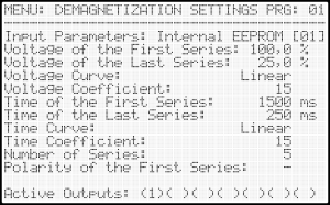
Input Parameters – by selecting the “Internal EEPROM” item, data is read from the internal memory of the control unit.
Polarity of the First Series – by default it is recommended to start the demagnetization waveform with negative polarity.
Active Outputs – by setting this value the user defines which outputs will be used for the demagnetization cycle.
For electromagnetic chucks, only a combination of active outputs 1 and 2 can be selected.
For electro-permanent chucks, any combination of active outputs can be selected. Only the electro-permanent chucks on the selected outputs are demagnetized during the demagnetization cycle.
All other parameters have no effect on the resulting demagnetization cycle – they are protected by the supplier.
The generation of custom demagnetization waveforms is described in the following section of the user manual.
EXAMPLE 7: Creating a custom demagnetization waveform using the algorithm
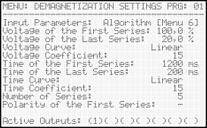
Input parameters – by selecting the “Algorithm” item it is possible to define the starting and ending point of the demagnetization curve. The algorithm is used to calculate the entire curve from these starting points.
The demagnetization curve can be linear or non-linear. A non-linear waveform can be defined by a coefficient.
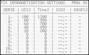
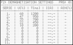
In MENU F2 it is possible to display the calculated demagnetization curves – it is not possible to edit the data in this menu.
The parameters of the individual demagnetization pulses are shown in detail in the table.
1st demagnetization pulse: -100%/1200ms
2nd demagnetization pulse: +80%/950ms
3rd demagnetization pulse: -60%/700ms
4th demagnetization pulse: +40%/450ms
5th demagnetization pulse: -20%/200ms
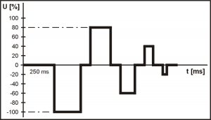
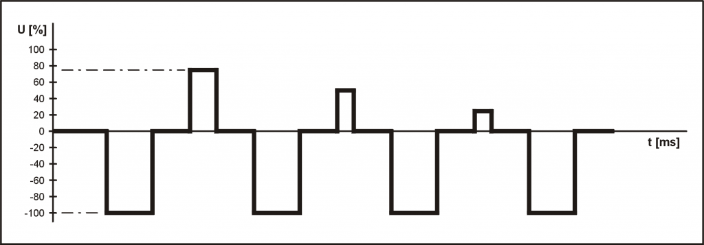
This picture shows the demagnetization cycle according to the specified algorithm.
The demagnetization process contains 5 demagnetization pulses.
The polarity of the first pulse is negative and for the following pulses the polarity alternates.
This is a symmetrical demagnetization which is suitable for standard electromagnetic chucks.
This demagnetization setting works with fixed voltage values of demagnetization pulses.
The following example demonstrates the special “P1” function, which allows to dynamically change the voltage of the demagnetization pulses depending on the position of the potentiometer P1 on the control box.
Using the “P1” function, it is possible to ensure that the voltage of the demagnetizing pulses will never be higher than the voltage at which the electromagnetic chuck was magnetized. The electromagnetic chuck is protected from damages due to overvoltage and the control unit from possible overload.
!!! Important notice !!!
All changed parameters must be saved immediately in MENU 8 – LOAD/SAVE DATA – Save Current Settings.
EXAMPLE 8: Creating a custom demagnetization waveform using the algorithm with the special function “P1”
Using the function “P1” it is possible to ensure that the voltage of the first demagnetization pulse is the same as the voltage at which the electromagnetic chuck was magnetized.
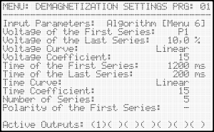
This image shows the activation of the “P1” function.
In the Input Parameters item, the value “Algorithm” must be selected and the symbol P1 must be set on the following line Voltage of the First Series.
To display the P1 symbol, set the minimum value with the down arrow and confirm this selection by pressing the ENTER key.
To verify the correct function, it is possible to set the output voltage to a value of e.g. 60% using potentiometer P1 – this value can be displayed in MENU F1 .
By switching to MENU F2 it is possible to display the demagnetization data.
The table shows the recalculated voltage of the individual demagnetization pulses.
The voltage of the first demagnetization pulse will always correspond to the specified output voltage according to the rotation of potentiometer P1 and the voltage of the next pulses is always recalculated before starting the demagnetization cycle. The “P1” function can be verified by turning potentiometer P1 to the required position and pressing the F2 key to recalculate the data.
Using the “P1” function, it is possible to ensure that the voltage of the demagnetizing pulses will never be higher than the voltage at which the electromagnetic chuck was magnetized. The electromagnetic chuck is protected from damages due to overvoltage and the control unit from possible overload.
!!! Important notice !!!
All changed parameters must be saved immediately in MENU 8 – LOAD/SAVE DATA – Save Current Settings.
EXAMPLE 9: Creating a precise demagnetization waveform using the algorithm
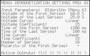
For precise demagnetization of higher quality materials it is recommended to choose a demagnetization waveform with multiple pulses – in this example 10 demagnetization pulses (series) are used.
It is recommended to demagnetize bigger workpieces with longer demagnetization pulses and higher voltages.
The output voltage should not be higher than the maximum allowed voltage of the electromagnetic chuck.
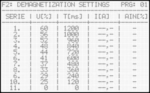
By switching to MENU F2 , the demagnetization data can be displayed.
From the displayed table it is evident that the demagnetization waveform consists of 10 pulses.
The first demagnetization pulse is negative – see Polarity of the First Series.
The values of voltage and pulse times decrease linearly.
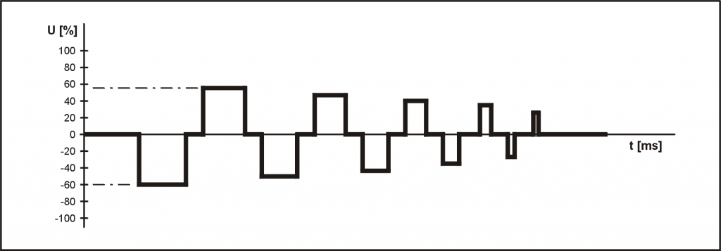
EXAMPLE 10: Creating a user demagnetization waveform
This example shows the control unit setup in user demagnetization mode.
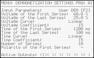
In the Input Parameters item, it is necessary to select the value “User DEM”.
This LCD screen allows you to set the First Series Polarity and Active Outputs.
All other parameters have no effect on the resulting demagnetization waveform.
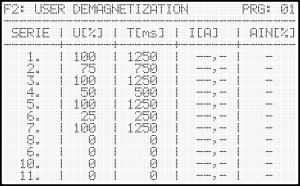
By switching to MENU F2 it is possible to VIEW and EDIT the demagnetization data.
From the displayed table it is evident that the demagnetization waveform contains 7 pulses.
The parameters of the individual pulses can be freely edited.
The following picture shows the resulting demagnetization waveform.
By selecting user demagnetization, any demagnetization waveform can be generated.
!!! Important notice !!!
All changed parameters must be saved immediately in MENU 8 – LOAD/SAVE DATA – Save Current Settings.
Contents of this document are spiritual property of ATHEA Microsystems s.r.o. Company. Without a former written consent of ATHEA Microsystems Company no part can be copied or multiplied in any possible way (printing, photocopy, microfilm or any other way), placed in the information system or transmitted in another form or by any other means.
ATHEA Microsystems Company cannot assume any legal responsibility nor provide any guarantee against using of false information with its following consequences. Claims to compensation based on modifications, mistakes or omissions are impossible in principle.
ATHEA Microsystems Company reserves its right to modify and improve the product described in this user manual anytime without previous notice. All registered or other trademarks used in this user manual are the property of their owners. By mentioning them no property rights ensuing from them are challenged.
ATHEA Microsystems is the registered trademark – Office of Industrial Property, trademark No.249691.