DESCRIPTION OF MENU ITEMS
MENU 1 – LANGUAGE SELECTION

On this LCD screen it is possible to switch the language used in the menu of the control unit.
—
Notice:
Other languages can be added by contacting technical support at email: athea@athea.cz.
MENU 2 – OPERATIONAL MEASUREMENT

This LCD screen displays the operating parameters entered by the user or the operating variables measured by the control unit.
All measured values are only approximate and without specified tolerance. Measured values can be calibrated in MENU 12 – Service Settings.
Calibration can only be performed by users with higher user permissions.
Input voltage (U1) – value shows the supply voltage at the input terminals L1-L2(N) of the control unit. This is an approximate value.
U1 Period – Actual – the current measured value of the input voltage period U1. This value is derived from the frequency of the power supply network. The controller adapts to the supply voltage parameters and is able to operate with both 50 and 60 Hz voltages.
U1 Period – Set – working value of the period. This value is updated each time the controller is connected to the power supply. The controller can operate with a measured or fixed period value. In extremely busy power supply networks, the control unit may not measure the voltage period correctly – in these cases, the period value can be entered manually in MENU 12 – Service Settings – Period U1 – Constant.
ADC Current Transformer – value of the output current from the A/D converter in the range of 0 to 4095.
0 A Current Transformer – value of the A/D converter current corresponding to the output current 0 A.
Max. Allowed Output Current – maximum permissible value of output current through the electromagnet. This value is set at the factory and cannot be changed.
It is not permitted to load the control unit with a higher current than the maximum permitted output current – this may cause irreversible damage to the control unit. When the maximum permitted current is exceeded, the control unit reacts by disconnecting the contacts of the safety relay RELAY RE1 and this state is stored in the memory of the control unit.
Max. Measured Output Current – maximum value of output current recorded during magnetization.
Electromagnet Temperature – the control unit is equipped with circuits for measuring the temperature of the electromagnet. For correct operation, the electromagnet must be equipped with an NTC1000 temperature sensor. This sensor must be connected to terminals AN1 and AN2.
Residual Magnetism – the control unit is able to process data from an external measuring module with a Hall probe. This probe is connected to the RS485 bus. The obtained data are displayed by the control unit in MENU F2 together with the demagnetization waveform data, which makes it easier for the user to create his own demagnetization waveform.
Set Output Voltage – value from potentiometer P1 on the control box.
Actual Output Current – the measured value of the output current by the electromagnet.
MENU 3 – PROGRAM SELECTION

On this LCD screen you can switch between the different programs.
If Program 1-4 is selected, it is not possible to switch programs on the control box.
If External Signal is selected, the switch on the control box is activated. This allows the machine operator to switch programs according to actual requirements.
MENU 4 – ELECTROMAGNET TYPE

This LCD screen allows to switch the type of electromagnet that is connected to the control unit.
Electromagnetic chuck – in magnetisation mode the electromagnet will be permanently powered all the time during processing.
Electro-permanent chuck – in the magnetization mode the electromagnet will be magnetized by a short electric pulse.
Important Notice:
Incorrect setting of the electromagnet type on this LCD screen can cause irreversible damage of the iPES control unit or connected electro-permanent chuck.
MENU 5 – MAGNETIZATION SETTINGS

On this LCD screen you can set the magnetization parameters.
The magnetization setting is different depending on the type of electromagnetic chuck.
The magnetization settings, including examples for each type of electromagnetic chuck, are described in a separate section of this user manual.
Maximum Voltage – maximum output voltage set by potentiometer P1 on the control box. The output voltage must not be higher than the rated voltage of the electromagnetic chuck.
Minimum Voltage – minimum output voltage set by potentiometer P1 on the control box. Low output voltage may cause insufficient workpiece clamping.
Magnetization Time – time of the magnetization pulse series in ms. This value is set only for electro-permanent chucks. For electromagnetic chucks this value is not important – it is not used.
Magnetization Delay – this delay is set only for electro-permanent chuck and is the delay between each series of pulses. This value is only used if the magnetizing cycle contains more than one pulse series.
Number of Pulse Series – setting the number of magnetization pulse series of the magnetization cycle. This value is only used for electro-permanent chucks and in most cases is set to “1 x”. For electromagnetic chucks this value is not important – it is not used.
Active Outputs – by setting this value the user defines which outputs will be used for the magnetization cycle.
For electromagnetic chucks, only a combination of outputs 1 and 2 can be selected.
For electro-permanent chucks it is possible to select any combination of outputs – only the selected outputs will be magnetized.
MENU 6 – DEMAGNETIZATION SETTINGS

On this LCD screen you can set the demagnetization parameters.
The demagnetization setting is different depending on the type of electromagnetic chuck.
The demagnetization settings, including examples for each type of electromagnetic chuck, are described in a separate section of this user manual.
Input Parameters – when setting the demagnetization, it is necessary to select how the data for the demagnetization process will be entered. There are 3 options:
- Internal EEPROM – selecting this item loads the demagnetization program data from the internal memory. This data is fixed in the processor memory – it cannot be viewed or edited and the LCD screen displays the text “Data locked”.
- Algorithm – by selecting this item it is possible to define the start and end point of the demagnetization curve. The algorithm is used to calculate the entire curve from these starting points. The demagnetization curve can be linear or non-linear. A nonlinear curve can be defined by a coefficient. The LCD screen displays the demagnetization data. The data cannot be edited in MENU F2, it must be edited in MENU 6 – DEMAGNETIZATION.
- User DEM – selecting this item allows the user to manually edit the demagnetization curve – voltage, length and number of demagnetization pulse series in MENU F2.
Voltage of the First Series – voltage of the first series of demagnetization pulses.
Voltage of the Last Series – voltage of the last series of demagnetization pulses.
Voltage Curve – the demagnetization voltage curve can be linear or non-linear.
Voltage Coefficient – setting the waveform of the non-linear demagnetization voltage curve.
Time of the First Series – time of the first series of demagnetization pulses.
Time of the Last Series – the time of the last series of demagnetization pulses.
Time Curve – the demagnetization pulse curve can be linear or non-linear.
Time Coefficient – setting the waveform of the non-linear demagnetization pulse curve.
Number of Series – the value defines how many times the polarity of the demagnetization pulses will change in the demagnetization procedure.
Polarity of The First Series – setting the polarity of the first series of the demagnetization procedure.
Active Outputs – by setting this value the user defines which outputs will be used for the demagnetization cycle.
For electromagnetic chucks, only a combination of outputs 1 and 2 can be selected.
For electro-permanent chucks it is possible to select any combination of outputs – only the selected outputs will be demagnetized.
MENU 7 – SAFETY FUNCTIONS

On this LCD screen it is possible to set the conditions for switching on/off the safety relay contact (RELAY RE1).
The current measurement is provided by an internal DC current transformer.
For temperature measurement, the connected electromagnetic chuck must be equipped with a temperature sensor.
MENU 8 – LOAD/SAVE DATA

This LCD screen allows you to read/save data to the internal memory of the control unit.
All settings are stored by the control unit even when the power supply is switched off.
Save Current Settings – selecting this item will save the data for the currently selected program. The currently selected program is displayed in the upper right corner of the LCD display. All saved data relates only to the currently selected program.
No manipulation of the PRG switch on the control box is allowed before saving data. Any manipulation of the PRG switch on the control box will cause the data of the newly selected program to be loaded from memory and overwrite any unsaved data.
Load Default Settings – selecting this item will load default data – applies only to the currently selected program.
Copy Current Data to All PRGs – selecting this item will copy data from the currently selected program to all other programs. Be careful when selecting this item – it will overwrite the data stored in all programs.
Download Data from HTTP Server – this item allows to update the settings of the control unit via the Internet connection.
For correct function it is necessary to enter the IP address of the server and the communication port in MENU 10 – HTTP Server Settings. All details are available on the website www.iPES6030.com. The update file is generated by the supplier or end customer on the manufacturer’s server.
To generate the update file, follow these steps:
1. Connect the iPES6030 control unit to the Internet via the ETHERNET connector.
2. Enter the address www.ipes6030.com into an internet browser.
3. Register the control unit by entering the serial number, e-mail address and access password.
4. On the login page, enter the serial number of the control unit, the registered e-mail address and the password.
5. On the displayed page, you can update the parameters of the control unit and generate an update file by pressing the “Generate update file” button.
6. On the iPES6030 controller, in MENU 8 – LOAD/SAVE DATA, select Download Data from HTTP Server.
7. Wait until the message „File downloaded successfully“ is displayed on the iPES6030 control unit LCD.
MENU 9 – RS485 COMMUNICATION

This LCD screen allows you to enter the parameters of the RS485 communication bus.
This interface is used for connection:
- intelligent control box
- the master control
- Hall probe
Multiple iPES control units can be controlled in parallel mode via the RS485 bus.
MENU 10 – HTTP SERVER SETTINGS
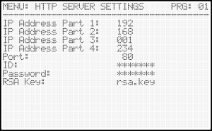
This LCD screen allows you to enter the Ethernet network parameters.
These parameters are necessary for the correct function of updating the controller via the internet connection.
The ID, password and RSA key fields are not necessary – they are specified by the manufacturer.
MENU 11 – USER PERMISSIONS

This LCD screen is available only to users with higher user permissions.
User permission settings are accessible after entering the ID and password in MENU 13 – Service Password.
Through these preferences, it can be specified which settings of the control unit will be accessible to the normal user and which will be password protected.
In this way, the control unit settings can be protected to prevent unauthorized changes that could cause damage to the control unit or the electromagnetic chuck.
Locked items will be inaccessible to unauthorized persons and cannot be read or edited. The supplier has the option to make the magnetization and demagnetization settings unavailable to normal users – these settings may be the subject of studies, experiments or long-term development and will be hidden to unauthorized persons.
MENU 12 – SERVICE SETTINGS

This LCD screen is available only to users with higher user permissions.
User permission settings are accessible after entering the ID and password in MENU 13 – Service Password.
The service settings are used for calibrating the measuring circuits and control unit optimization.
P1 MIN – Calibration – used for calibration of the A/D converter. It sets the lower limit of the analog signal used for output voltage regulation. Calibration is performed by turning potentiometer P1 to the MIN position and long pressing the ENTER key to update the minimum value.
P1 MAX – Calibration – is used to calibrate the A/D converter. It sets the upper limit of the analog signal used to regulate the output voltage. Calibration is performed by turning the P1 potentiometer to the MAX position and long pressing the ENTER key to update the maximum value.
By default, the output voltage is regulated by potentiometer P1 on the control box, which outputs a voltage of 0 to 10 V DC (MIN = 0V = 0% and MAX = 10V = 100%). Using this constant, it is possible to recalibrate the analog input e.g. (0V = 0% and 5V = 100%).
Voltage U1 – Calibration – is used to calibrate the value of the Input voltage (U1) displayed in MENU 2 – OPERATING PARAMETERS.
Temperature – Calibration – used to calibrate the temperature of the external temperature sensor.
U1 Period Measurement – use this value to set whether the controller will perform a period analysis of the supply voltage (AUTO) at restart or if a fixed constant will be used.
ENABLE IN – this parameter enables or disables the ENABLE IN input, which can be used to block the start of magnetization/demagnetization.
Short Circuit Test – this parameter activates or deactivates the short circuit test function on the controller output when starting magnetization/demagnetization. The control unit must be equipped with an additional card that is not a standard part of the product.
Relay/Contactor Delay – this constant defines the delay of the contactors that switch the polarity of the output voltage and switch the outputs to be magnetized or demagnetized.
Maximum Current – the maximum current allowed through the electromagnet. This value is specified at the factory and cannot be changed. When the maximum permitted current is exceeded, the control unit reacts by disconnecting the contacts of the safety relay RELAY RE1 and this state is stored in the memory of the control unit.
Current Trans. – Coefficient – used for calibration of the DC current transformer. This value is factory set and cannot be changed.
0A Current Transformer – used for calibration of the current transformer. This value is factory set and cannot be changed.
Period U1 – constant – this is a constant that is used when the controller is unable to analyze the input voltage period or this function is disabled. The control unit analyzes the power supply network at each power-up (restart).
Serial Number – this is the serial number of the control unit. This value is specified at the factory and cannot be changed. The serial number of the control unit is also used to log into remote management, which allows updating the control unit settings via the Internet.
MENU F1 – OPERATIONAL MEASUREMENTS

By pressing the F1 key on the front panel of the control unit it is possible to display the current operating information – the required output voltage, output current through the electromagnet and the status of the RELAY RE1 contacts.
MENU F2 – DEMAGNETIZATION SETTINGS

By pressing the F2 key on the front panel of the control unit, the demagnetization waveform table can be displayed.
The table is divided into 5 columns:
Series – order of demagnetization series
U[%] – required output voltage
T[ms] – required pulse time
I[A] – max. measured output current
AIN[%] – measured value of ext. sensor
- Progress of Demagnetization:

The data in the table changes depending on the input data in MENU 6 – DEMAGNETIZATION.
- MENU 6 – Demagnetization Settings:

The user defines the voltage and time of the first and last demagnetization pulses. The demagnetization process is automatically calculated depending on the number of series.
The polarity of the 1st series can be changed.
In this case, the control unit will perform demagnetization only on the DC OUT1 output.